|
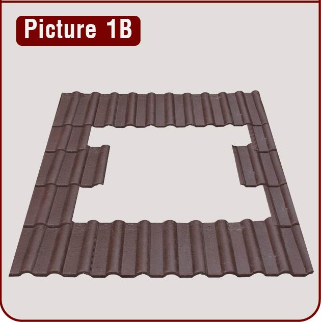
Step 1A: STRAIGHT BOND LAYING
Locate and remove 12 pieces of roof tiles for straight bond laying as marked.
Note: For optimum effect, install the Zepher unit as high as possible, 3rd tiles from the top (ridge or wall). Make sure tiles opening is clear of the rafters and cut off any ceiling of roof panels, sarkers or insulations that may obstruct air flow. Ensure all cutting is performed nicely if it can be seen from the bottom. Do not cut any battens or structural part of the roof or ceiling.
|

|
|
Step 1B: CROSS BOND / STAGGERED LAYING
Locate and remove 10 pieces of roofing tiles for staggered laying as marked.
Note: For optimum effect, install the Zepher unit as high as possible, 3rd tiles from the top (ridge or wall). Make sure tiles opening is clear of the rafters and cut off any ceiling of roof panels, sarkers or insulations that may obstruct air flow. Ensure all cutting is performed nicely if it can be seen from the bottom. Do not cut any battens or structural part of the roof or ceiling.
|
|
|
Step 2
Position the flashing in the opening, making sure the turret opening is positioned between the rafters and clear of any other obstructions. Avoid rafters to be in between the openings for optimal air flow. (Picture 2)
Tip: Always try to place one side of the flashing in line with the tile joint line. This will help to reduce the number of tiles to be cut which sit over the wing sections.
|

|
|
Step 3
Once the flashing is correctly positioned, bring the front skirt of flashing up against the back edges of roof tiles and trace profile of roof tiles onto the front skirt of the flashing.(Picture 3)
Note: Make sure the bottom face of the wing sections are level with the highest section of the front roof tiles. The same also applies with clay roof tiles.
|

|
|
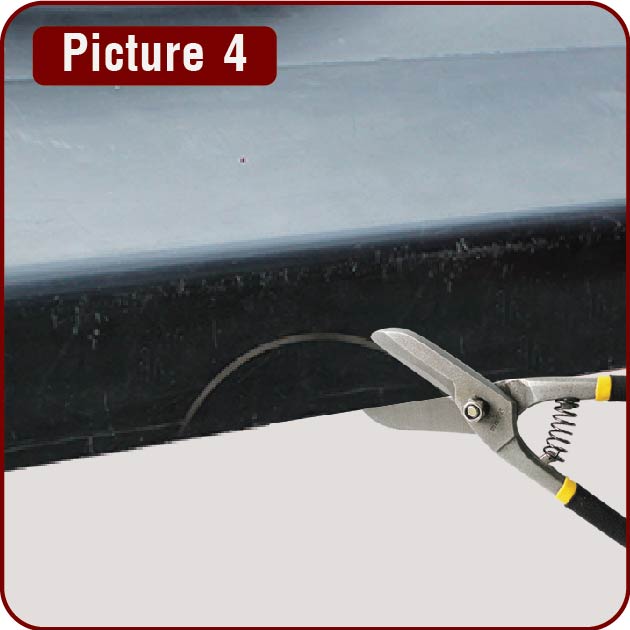
Step 4
Remove the flashing and cut out marked sections on the front skirt using tin snips. Right hand and left hand tin snips may be required occasionally for an accurate cut. (Picture 4)
Note: After tin snipping the profile of the clay or concrete tile, any accidental larger gaps should be sealed off with silicone adhesives. Black silicone adhesives (preferred) should be used for black or very dark coloured roofs and gray silicone for lighter coloured roof.
|
|
|
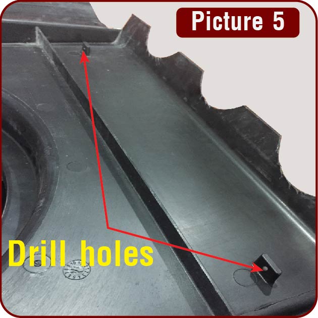
Step 5
Drill two 6mm holes through the nips the under the front of the flashing. This is to accommodate cable ties. (Picture 5)
|
|
|
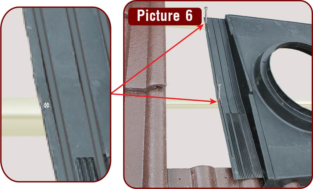
Step 6
Fit the flashing into position, making sure the front skirt of the flashing is in line with the front edge of the first 2 side tiles or position the transition line of both side wing section along the front edge of the center battens. Secure the flashing to center and top battens with 4 roof self tapping screws (supplied), placed at most outer edges of the wing sections. Ensure that the wing sections are not sloped sideways otherwise water may leak in. (Picture 6)
|
|
|
Step 7
Secure front middle section of the flashing with cable tie passing through drilled hole nips and around tile batten. Create a loop at the batten first then pass through another cable tie through hole of nips rib and the cable tie loop.
Tip: Do not over tighten the cable tie, as this may change the shape of the top front section of the flashing. (Picture 7)
|

|
|
Step 8
Drill a 6mm hole at outer edge of the wing section just behind the back edge of the lower roof tiles. Then pass cable tie through hole and around tile batten. Carefully tighten cable tie to form front wing section over shape of roof tile. (Picture 8)
|

|
|
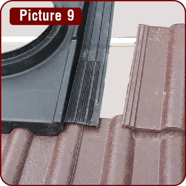
Step 9
Proceed to fit back full tiles where possible. (Picture 9)
|
|
|
Step 10
Where there is less than a full tile to fit; measure and cut tiles to suit opening, making sure there is minimal gap between tile and side section of flashing. Once side tiles are placed, fit tiles over the top-back section of the flashing. (Picture 10)
Note: If cut tiles can't be locked into place, they will need to be secured to prevent them from sliding out. This can be done by applying a "blob" of silicone adhesive only at the very back edge on the overlapping joint of tiles.
|

|
|
Step 11
In order to have the roof tiles which sit over the wing sections to sit correctly, it may be necessary to remove the batten lugs at back of the roof tile.(Picture 11)
|

|
|
Step 12
To prevent the noses of the 2 tiles which sit on the center flashing to protrude upwards, it is best to remove or round off the weatherchecks and supporting nibs as shown in picture. This will allow the tiles sit evenly with existing tiles. (Picture 12)
|

|
|
Step 13
Install the Zepher over the neck of the main center flashing. The Zepher must sit perfectly over the recessed neck of the flashing. (Picture 13)
|

|
|
Step 14
To secure the Zepher, drill three 3mm holes through the neck of the Zepher and the flashing. Then rivet or screw the neck of the Zepher to the neck of the flashing. The Zepher can now operate without any maintenance. (Picture 14)
|

|
|
Step 15
To finalize the installation, pick up and remove all debris from the installation thoroughly and wash the roof by hosing down any dust or fine debris from cutting any tiles. Any broken tiles from the result of accidental stepping or damages must be replaced in order to avoid any future leakages. Ensure solar module is cleaned and no stickers or fingerprints on it. (Picture 15)
|
|
THE UNIVERSAL FLASHING SET INCLUSIVE OF
- 1pc Universal Flashing
- 8pcs of Cable Ties
- 7pcs of Self Tapping Screws
|